From physical to application: Breaking down the 7 layers of the OSI model

What do disco music, Star Wars and Saturday Night Live all have in common? The 1970s. A decade jam-packed with social and technological change, which also happened to bring us advancements in computing technology that would shape the way the entire world communicates.
At the time, computers were essentially very large, very slow, very powerful calculators, and while the ability to connect some in a Wide Area Network (WAN) existed, reach was very limited. As more networks developed, this problem became amplified, and members of the International Standardization Organization (ISO) began work on a set of common standards for networks that communicate with each other.
The Open Systems Interconnection (OSI) Model as we know it was published in 1984, and established common standards for interconnectivity, breaking the concept down into seven different layers, each with a specific function.
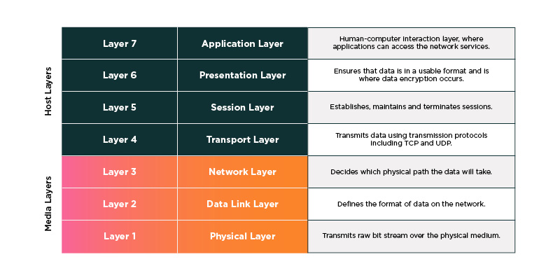 Figure 1: The Lumen 7-Layer OSI Model maps data flow from the cabling and physical media to the application functionality.
What is the OSI model and how does It work?
Each communication layer is built on top of the other, with the Media Layers (1-3) facilitating the physical transmission of data over connections. The Host Layers (4-7) which define how data is formatted and eventually presented to end users. Here’s a look at each layer in more detail.
Layer 1: Physical layer
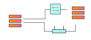
Figure 2: The Physical Layer provides connections between devices such as cables, switches and other hardware.
Layer 1 represents the physical connections between devices such as cables, switches and other hardware. These devices, or nodes, are responsible for transmitting series of bits, or bitstreams, which are the most foundational unit of data in computing.
Fiber optic cables that connect between locations help to make up an organization’s network backbone and are part of the Physical Layer.
Layer 2: Data link layer
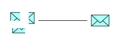
Figure 3: The Data Link Layer is responsible for the transfer of data between two devices on the same network.
Layer 2 is responsible for the transfer of data between two devices on the same network. Functions like formatting data packets, error detection and correction to ensure data integrity, and flow control occur at the Data Link layer.
Ethernet, which facilitates communication between devices in a local area network (LAN), is an example of a technology that operates at the Data Link Layer.
Layer 3: Network layer
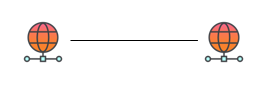
Figure 4: The Network Layer defines logical addresses for devices on a network and determines the best route for data to travel from one network to another.
At the Network Layer, logical addresses — the identifiers for devices on a network — are defined and the best route for data to travel from one network to another is determined.
The most common example of logical addressing is IP (Internet Protocol), a set of rules that establishes how data is sent and received over the internet. IP defines address formats, how data is broken down into packets and in some cases reassembled, and routing pathways. For example, your organization’s internet connectivity is facilitated at Layer 3.
Layer 4: Transport layer

Figure 5: The Transport Layer is where end-to-end communication between two devices happens.
The Transport Layer is where the end-to-end communication between two devices happens. Here, the rules established for packet delivery are executed, with data being broken down and reassembled according to transmission protocol. The most common are TCP (Transmission Control Protocol) which is reliable and connection oriented, and UDP (User Datagram Protocol) which is connectionless and speed oriented. Layer 4 is also responsible for managing data flow to prevent congestion, and checks for errors, requesting retransmission where necessary.
Layer 5: Session layer

Figure 6: The Session Layer establishes, manages and terminates connections between applications.
A session is essentially a temporary agreement between two devices or applications to exchange data for a specific period. Layer 5 is responsible for setting up, facilitating and ending sessions.
When you get on a video call, the session layer establishes the connection between your device and the others on your call, monitors the flow of audio and video so they are synced with the right timing, and terminates the connection at the end of your call to close out the session.
Layer 6: Presentation layer

Figure 7: The Presentation Layer makes information consumable for Layer 7 applications that will eventually be viewed by an end-user.
Layer 6 translates data between Layer 7 and the network. Responsible for data compression to help ensure speed and efficiency, and translation so that devices with different encoding methods can communicate, the Presentation Layer makes information consumable for Layer 7 applications that will eventually be viewed by an end user.
At the Presentation Layer, an email you send is encoded so it can travel without corruption to its destination, and once there will be decoded so that it’s readable.
Layer 7: Application layer
 Figure 8: The Application Layer is where the applications we use daily operate.
The Application Layer is where the applications we use daily, such as email and browsers, operate. You are currently experiencing an example of Layer 7 in action, facilitating communication between your browser and our web server so that you can read this blog.
Tying it all together
I don’t think the scientists and researchers of the 1970s could have imagined that the building blocks of networking would eventually play out in real-time communication via tiny touch screen computers we carry around daily. Thankfully, their dedication to establishing a common protocol for networks to communicate with each other laid the groundwork, and each of the seven layers of the OSI Model plays a part in nearly all our digital interactions today.
Although the OSI Model has endured the test of time, technology continues to develop rapidly. The demands on network infrastructure today are unprecedented with the vast amounts of data used, generated and transmitted by the generative AI applications taking up their station in the digital economy. And, as we get smarter in our use of technology, so do attackers looking to infiltrate weaknesses. The need for secure, efficient and powerful connectivity is absolutely crucial to success.
Explore our Networking Solutions to learn how we can solve the connectivity challenges you’re facing today.
This content is provided for informational purposes only and may require additional research and substantiation by the end user. In addition, the information is provided “as is” without any warranty or condition of any kind, either express or implied. Use of this information is at the end user’s own risk. Lumen does not warrant that the information will meet the end user’s requirements or that the implementation or usage of this information will result in the desired outcome of the end user. All third-party company and product or service names referenced in this article are for identification purposes only and do not imply endorsement or affiliation with Lumen. This document represents Lumen products and offerings as of the date of issue. Services not available everywhere. Lumen may change or cancel products and services or substitute similar products and services at its sole discretion without notice. ©2025 Lumen Technologies. All Rights Reserved.
Trending Now